- -------PRE
ENGINEERING CONCEPTUAL DESIGN AND PROMOTION SERVICES--------
|
-
-
| MARINEIMAGING/KENNEDY DESIGN - MAJOR REFIT AND
OVERHAUL OF A MEGA-YACHT |
-
-
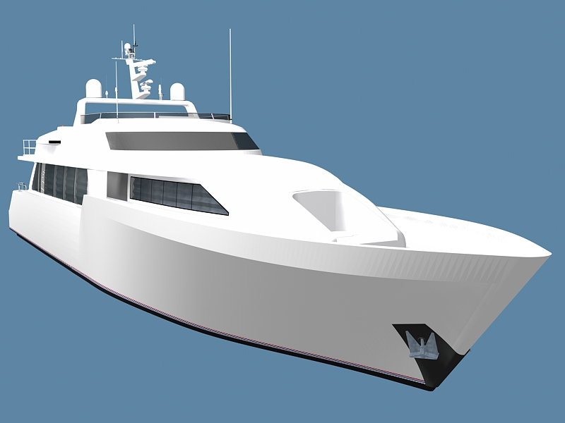
- The Planning Stage - For this high end mega-yacht visual appearance
is just as important as structural integrity, safety at sea,
and functionality. In order to show the visual impact of changes
that would occur to the vessel we would need an accurate model
developed, however, the new owner did
not have the original CAD files.
-
- I began developing the
3D model in preparation for planning the new arrangements and
radar arch. DNC of Mobile, AL later arrived and took their own
measurements as they would be developing the materials to build
and install the final mast system and bottom job. While mine
were to be dimensionally correct to insure integrity of the view,
theres had to be measured to fit a model which I had not seen
to replecate.
|
-
-
-
-
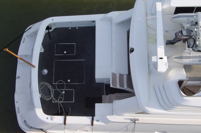
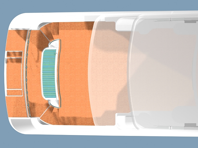
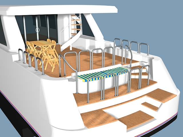
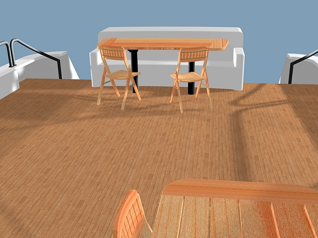
| Step
2 - To expedite the process we
began by developing only the cockpit area to show the owner and
agent different design ideas. Since we didn't know what the final
design would look like we used a generic wood pattern for the
teak deck. |
-
-
-
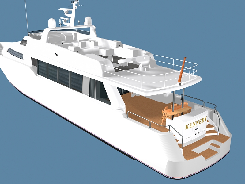
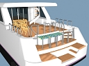 |
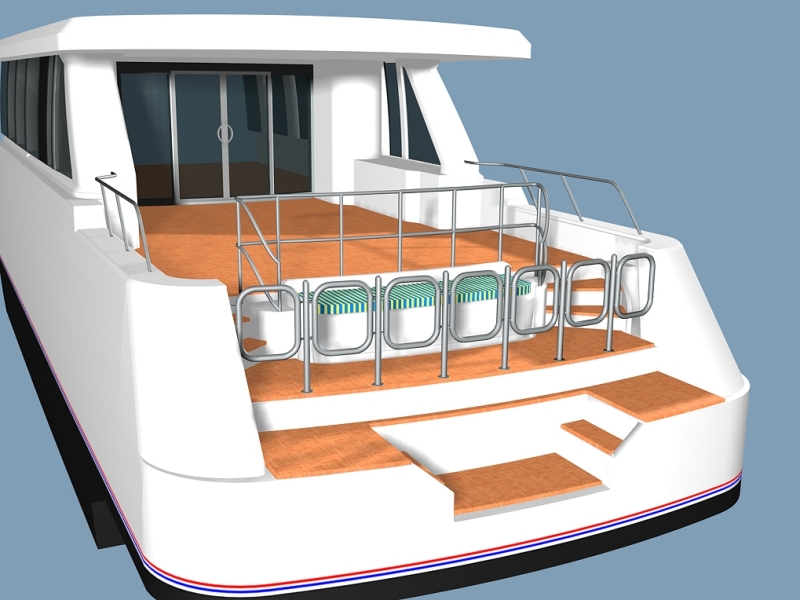
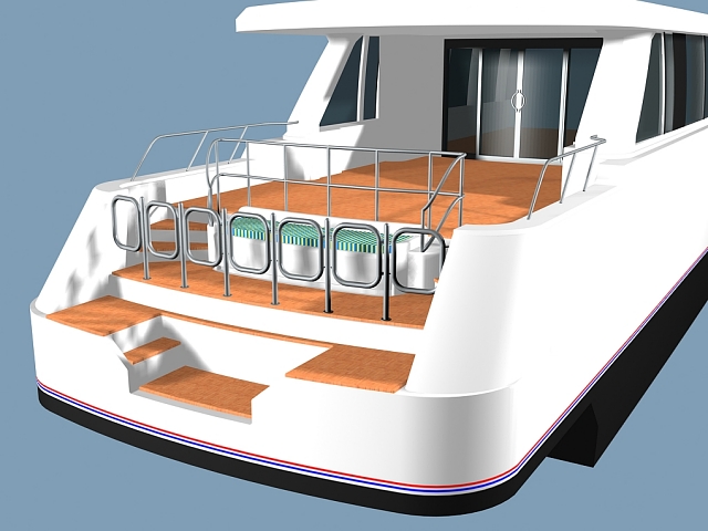
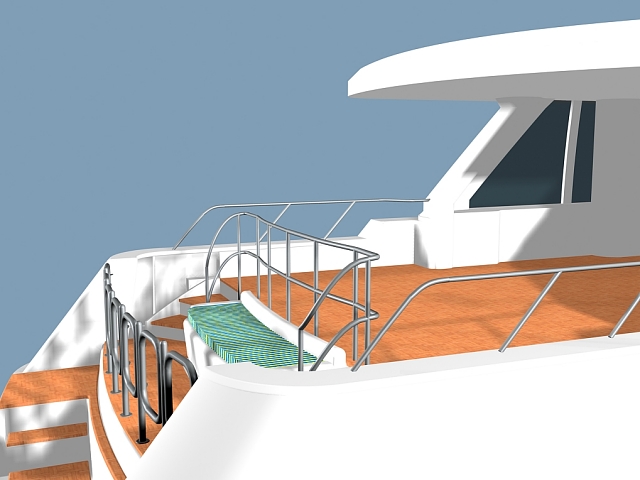
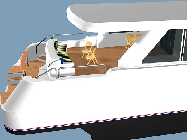
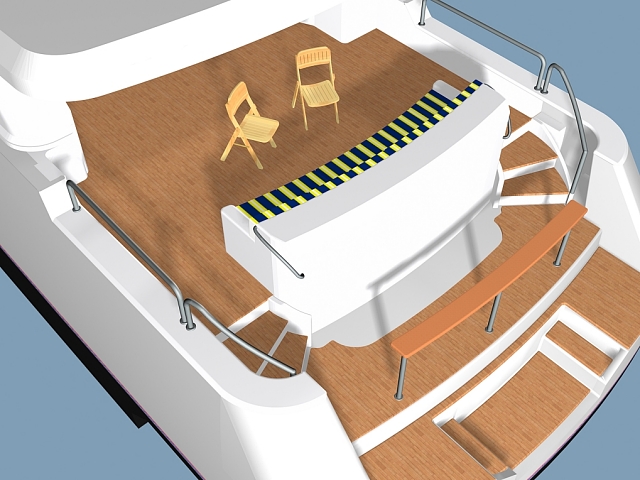
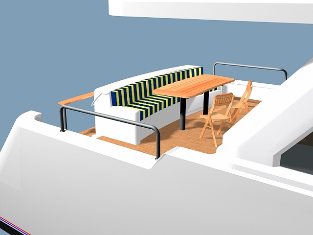
CONCEPTS for the After Deck
Section
These views are a collection of
in-process renderings that were built on top of the models first
stage. This section was also used to begin building out the remainder
of the yacht. At this point we were more interested in giving
the owner and agent ideas to work from.
|

|
-
-
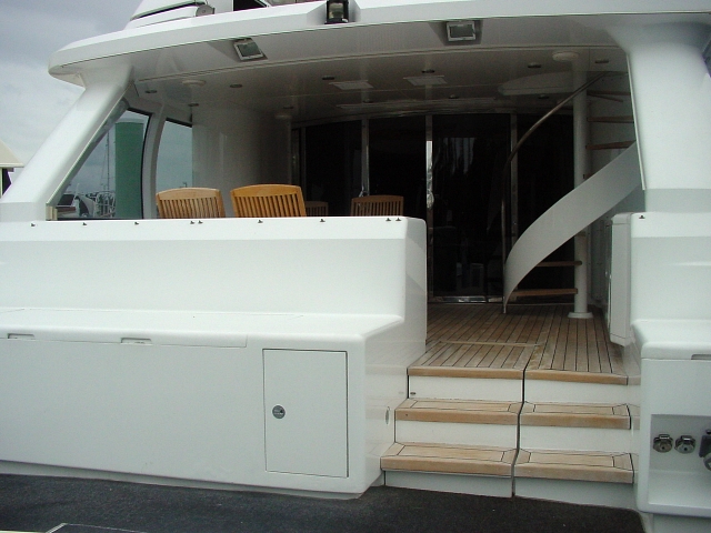
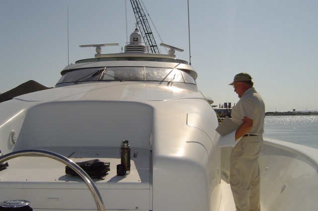
- Step 3 - After the yacht arrived at the
Kennedy Ship and Repair graving dock we began taking dimensions
and photos to continue developing the project for the client
to see well in advance of cutting away material.
|
 |
|
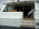
Before Image |
|
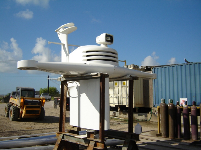
- As you can see in these
actual photos the stowage/freezers take up a large amount of
space on the lounge deck. These are to be removed.
-
- To do the job correctly
we must first measure and document the entire boat to make sure
that the 3D imaging is representative of the actual vessel.
|
|
|
|
Before Image |
|
-
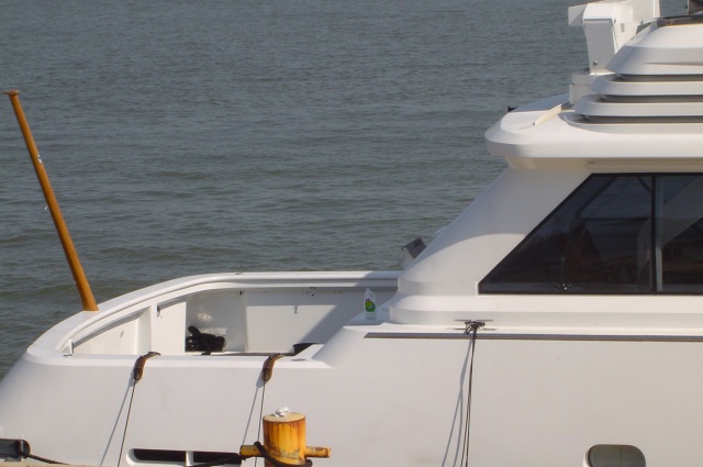
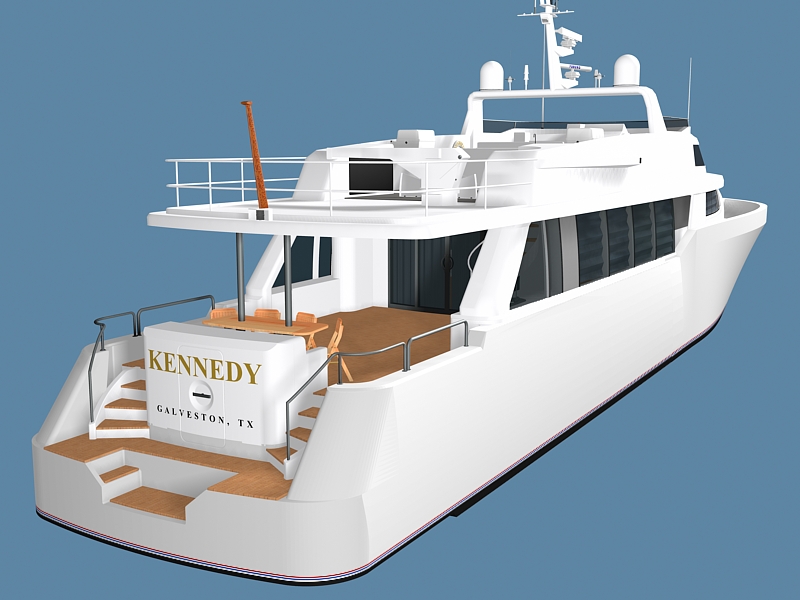
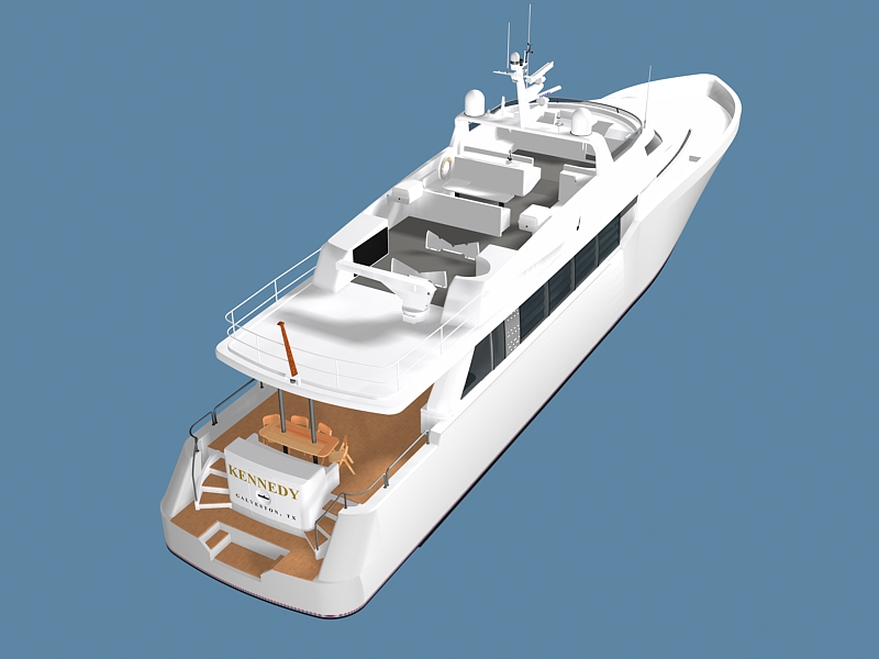
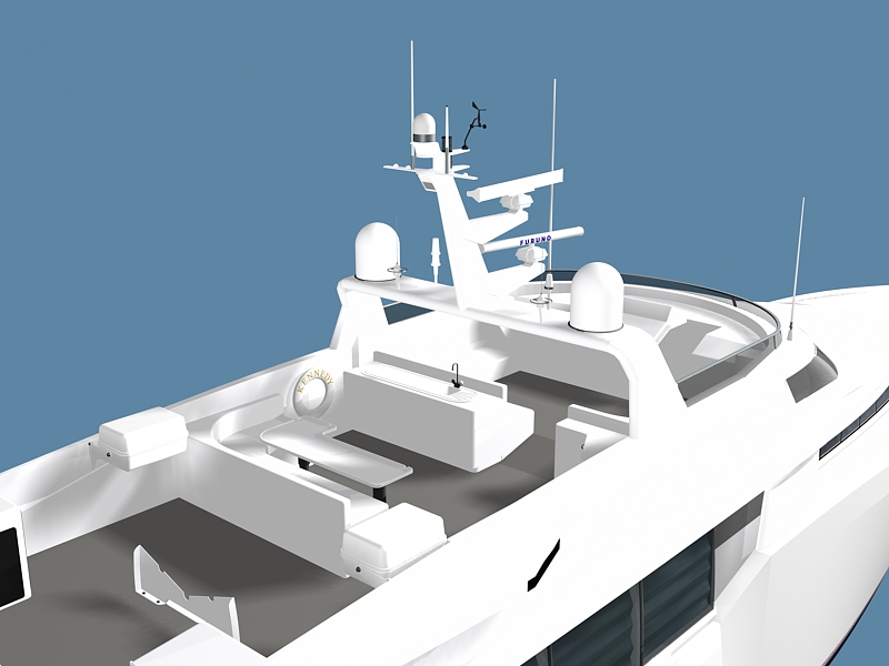
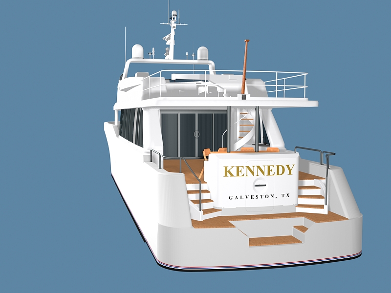
| Step
4 - We have now finished
a general overview of the entire yacht. The purpose of
this next group of renderings is to show how the radar arch and
the preferred cockpit design will change the overall appearance
of the vessel. (We replaced the actual vessel name and home port
to protect the clients identity but the style is to be the same.) |
-
-
-
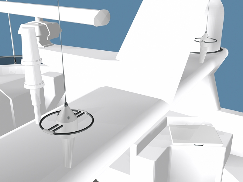
| At this
point we've eliminated the seat cushions until we can obtain
a color swatch from the client. In the last image you can see
some of the detail in the ring antenna closup. You can also see
how much is NOT shown in the closeup as the 3 dimensional facets
that make up the images become more visible. |
-
-
-
| These images,
along with matching AutoCAD drawings, have now gone to the naval
architect where they will be reviewd for fitting into their own
programs. Any major changes they suggest can be brought back
into the original drawings and imaged out for the client to review
if necessary. |
-
-
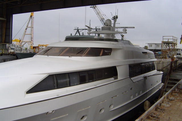
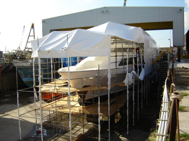
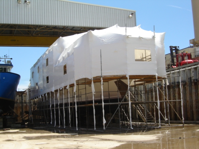
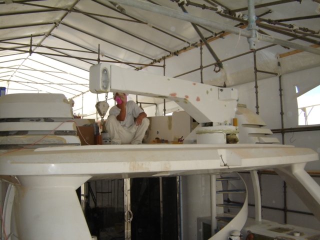
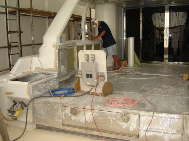
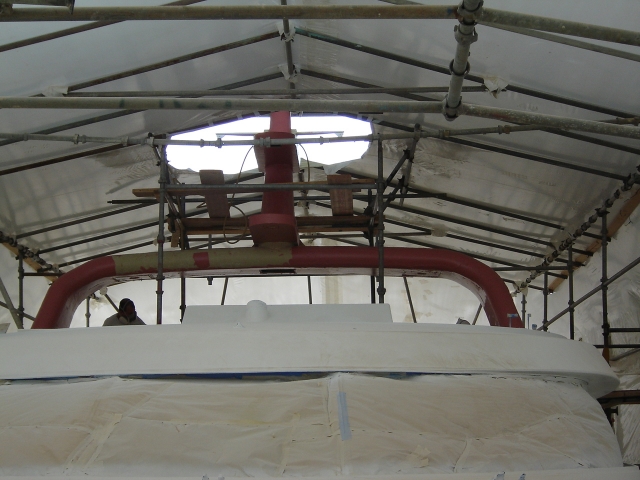
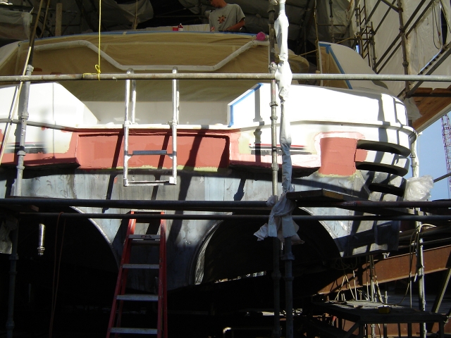
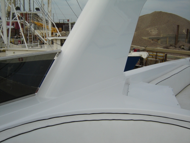
| The following
images show the progress up to the end of 2004. The old "T"
mast was removed and the entire vessel covered. The refrigerator
and storage boxes were removed along with the yachts windows.
Work was also started to sand down every blemish and rebuild
the surface to a matching height (fairing) before repainting
the entire vessel. |
-
-
-
-
-
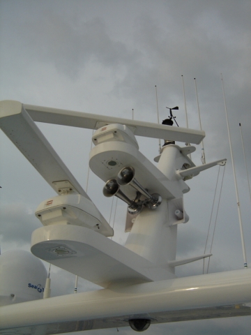
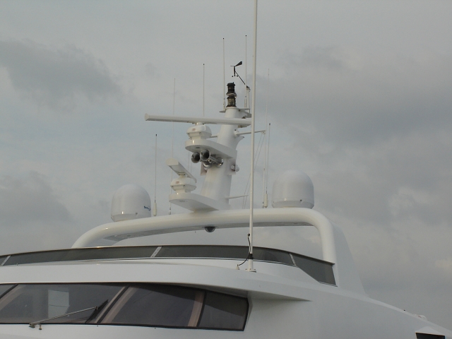
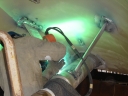
| Inside the
shop work on the new radar arch and mast began. It was later
installed in place of the old "T" mast. |
-
-
-
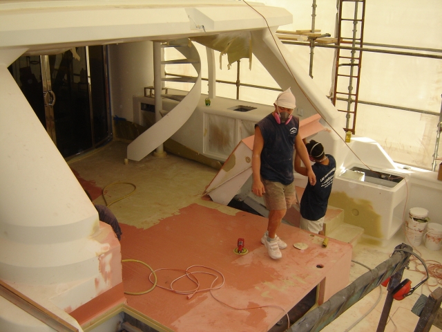
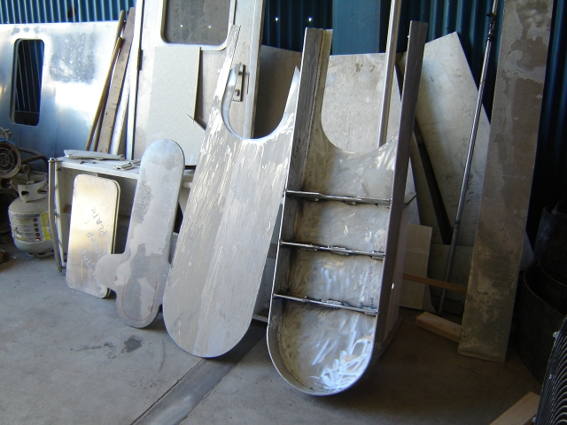
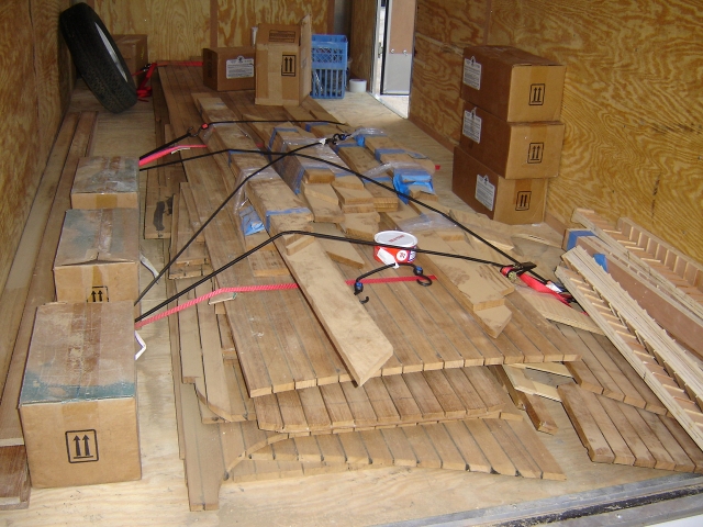
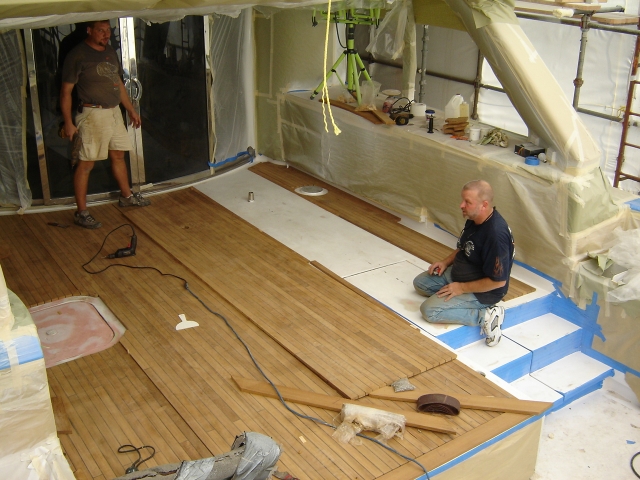
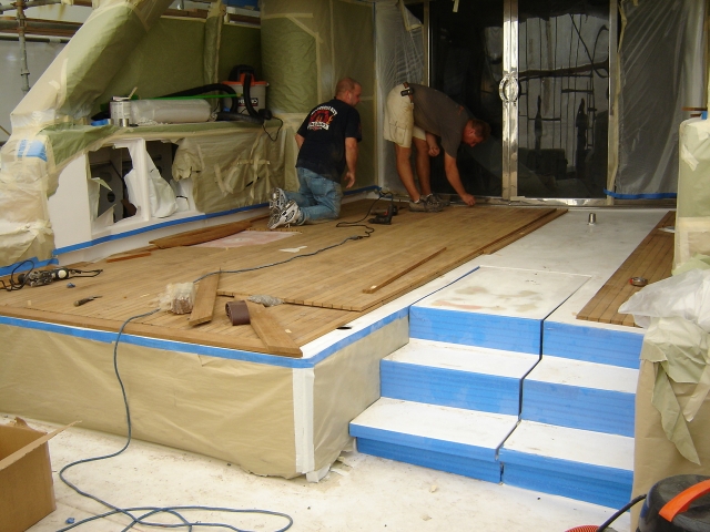
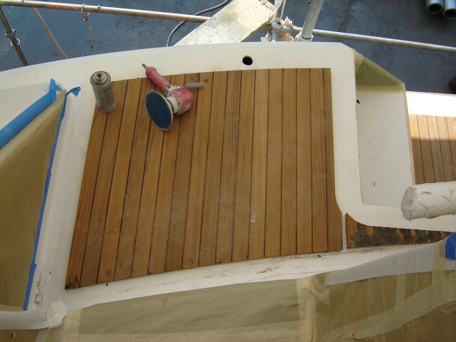
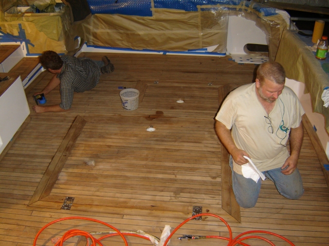
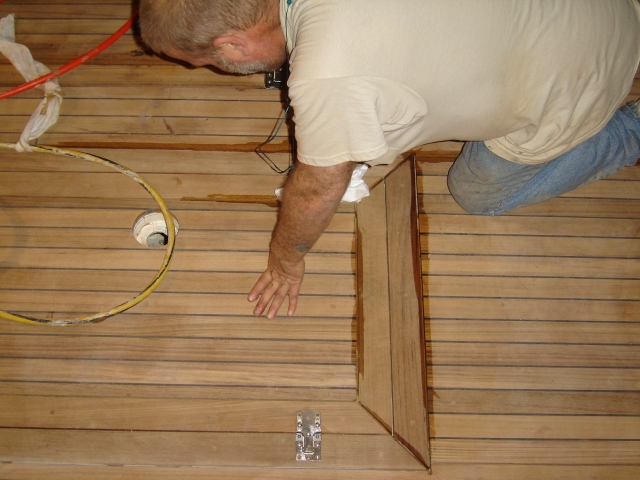
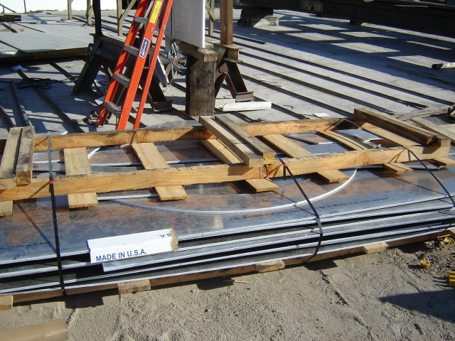
| Plans for
the new teak deck were made and sent off. As soon as the new
cockpit deck was faired the partially assembled teak deck arrived
in a trailer and installation began. |
-
-
-
-
-
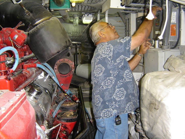
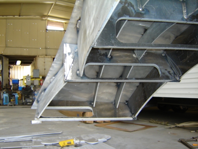
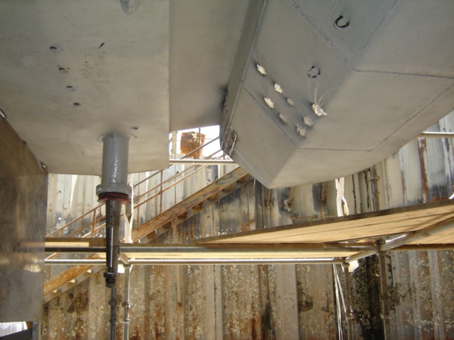
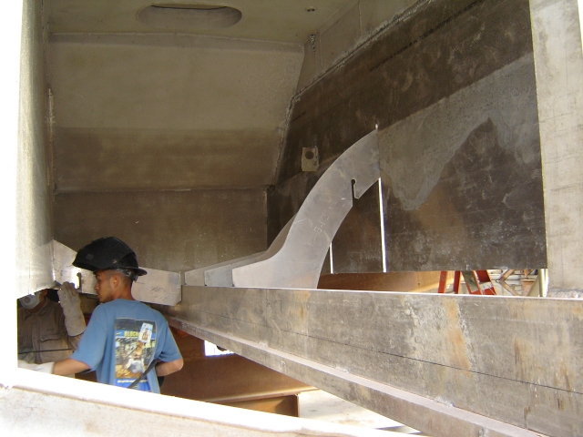
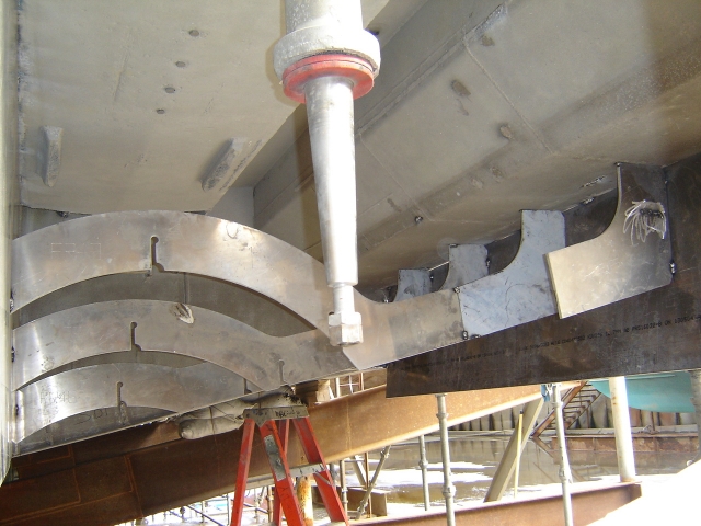
| Beneath
the hull the original surface drive system was completely removed
and tunnels installed along with new propellers and rudders.
The following shows progress made up to our departure in December. |
-
-
-
 |
 |
 |
| The surface drive system which
never worked to its potential was converted to a traditional
prop and rudder giving it 12-15 knots. |
|
-
-
-
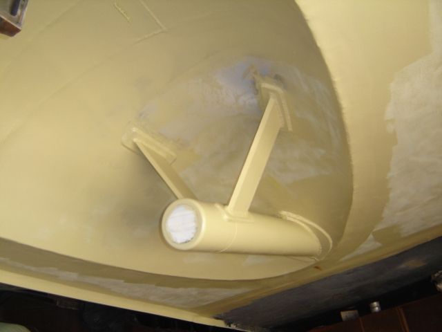
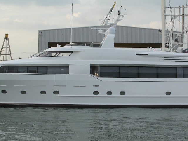
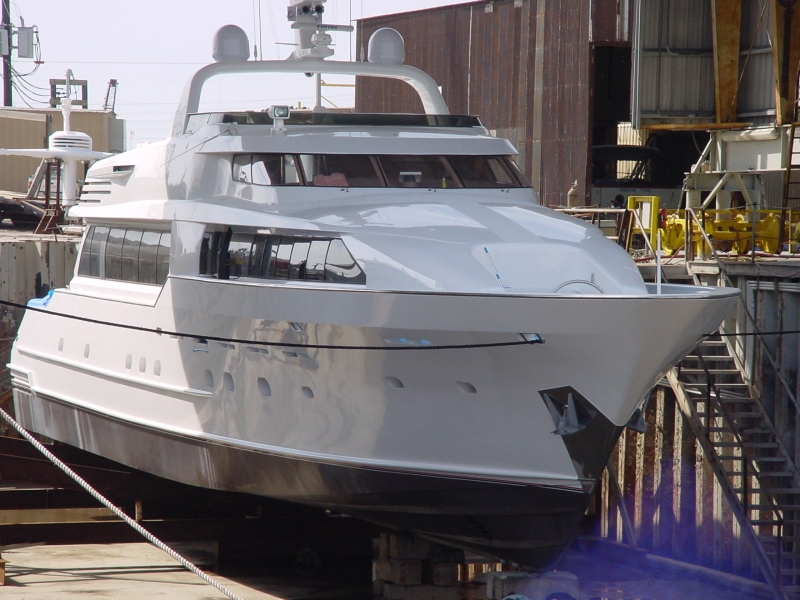
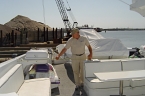
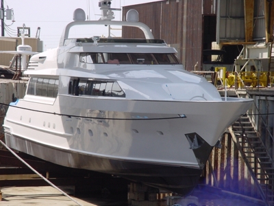
| And here
is the finished product in the graving dock and in the water.
A well pleased customer left with her to head back to the north
east. |
-
-
-
-
-
-
- ©
2016 c.r. watson - all rights reserved
- The
use of any trademarks, trademarked names, and/or copyrighted
information is stated
as a fact of record and is not
- intended
to imply endorsement of any kind. The use of any pictures, writings,
or materials from this site without
- express
written consent of Charles R. Watson dba Watson Enterprises aka
MarineImaging.com is forbidden.
|
|