- -------PRE
ENGINEERING CONCEPTUAL DESIGN AND PROMOTION SERVICES--------
|
-
-
| LASER SCAN TESTING THE PROCEDURE |
-
-
|
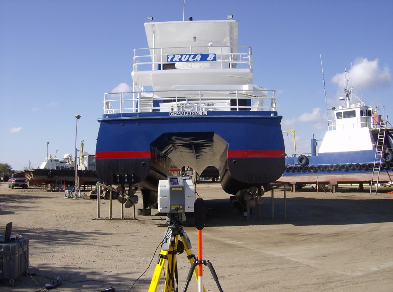
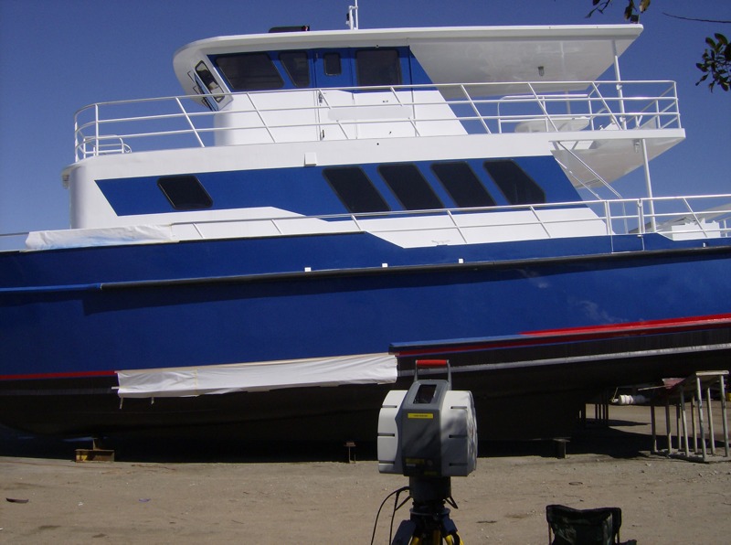
Before scanning the Fairfield Encounter we had
to prove the concept and test out the procedure. The scanning
crew needed a bit of training as they had never scanned a boat.
We set up a catamaran near their office and highlighted the concerns
they would face on the dry dock such as limiting where they could
set up the scanner and dealing with having to reach so much area
in a small distance with the bottom possibly being obscured. |
 |
-
-
| LASER SCAN TO AUTOCAD FOR SPONSON
FITTING |
-
 |
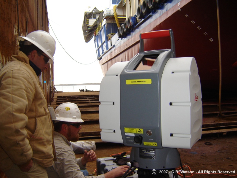
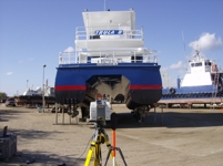
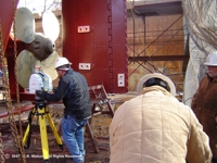
Now that we have the process down and the vessel
has arrived and loaded into the dry dock it is time to set up.
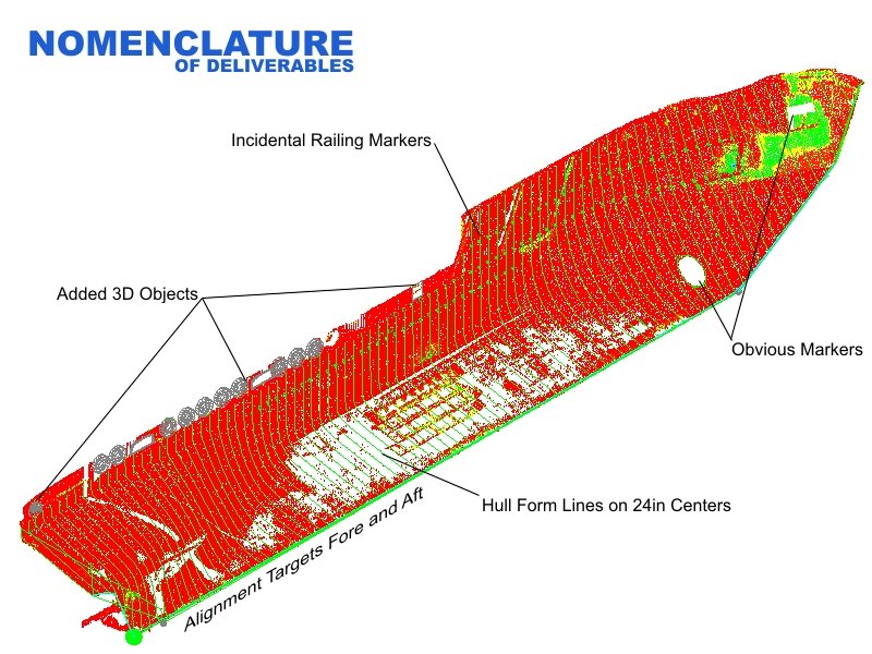
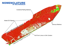
On the left the crew sets the laser scanner. On the right I have
laid out the nomenclature of a scan using the first original
scan in AutoCAD. The scanning process uses a triangulation method
to create the surface but we need to establish a fore-aft base
line and then other identifiers that would be relevant to picking
locations and to work around with the new frames. |
|
-
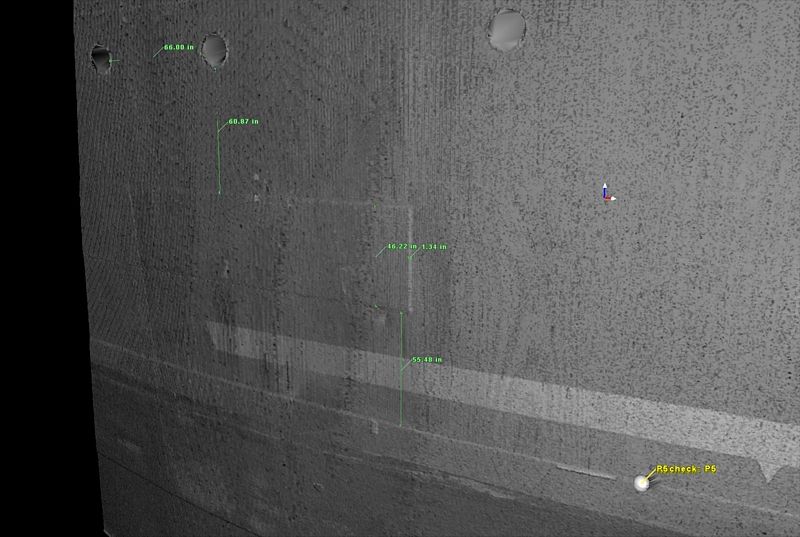
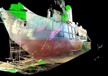 |
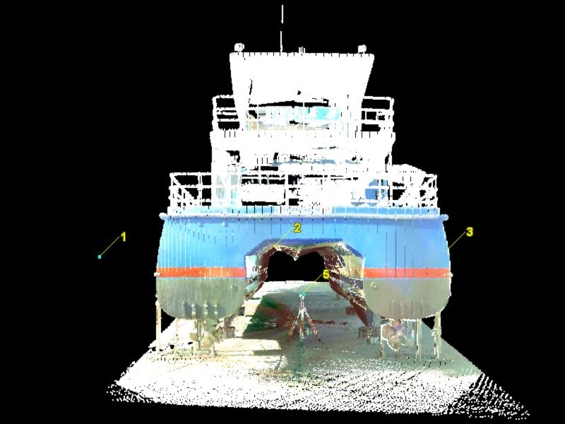
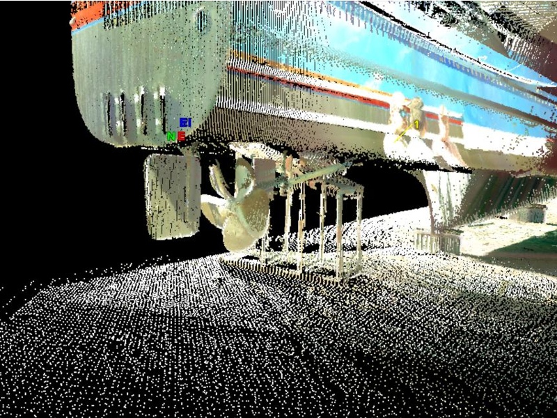
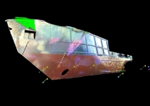
The scan produces a 3D image from the triangulated
cloud of points and applies a photo overlay (left) to identify
points of interest. In the right image you can see where plates
were welded onto the hull and even small collision dents. The
software used to interpret the data and make it work on 32bit
computers also allows measuring from point to point and mean
surface depths. |
|
-
 |
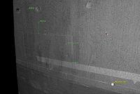
Once in the computer the operators cleaned up the
image to have only essential information the image was turned
off. Here (right) you can see the cloud data points. Where the
laser could not scan is a technical shadow. Such as the chain
in this image. The chain had been dropped in order to retrieve
and repair the anchor. In the image above left you can see the
chain hanging from the hawsepipe and the shadow behind it. During
cleanup the crew removed the chain but you can still see the
shadow. |
|
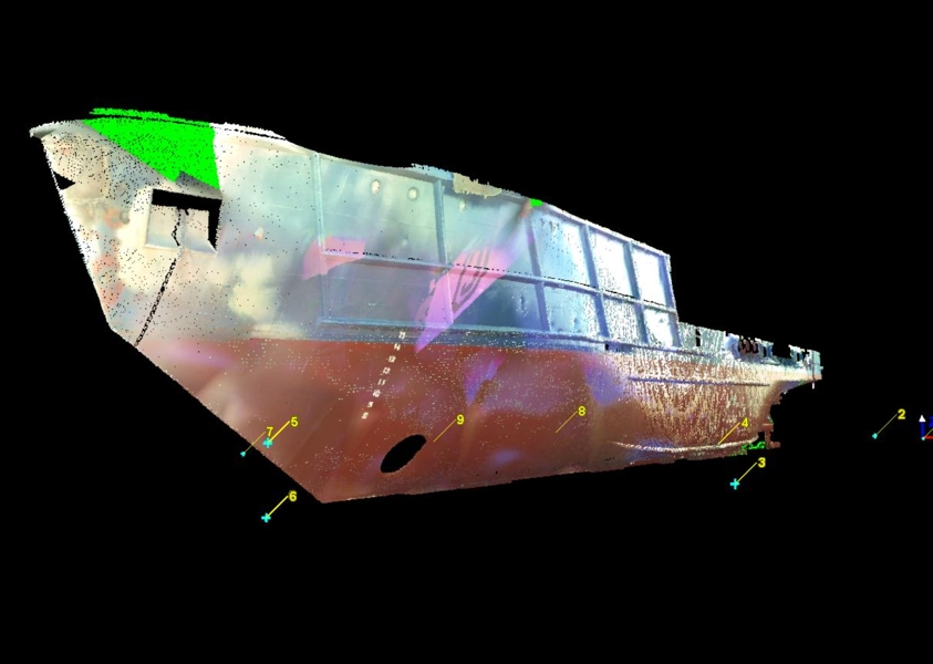
-
 |
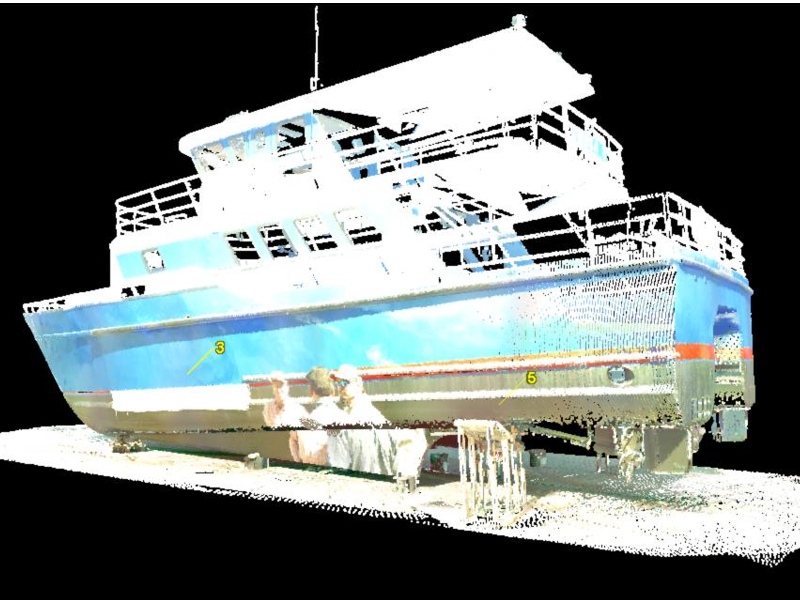
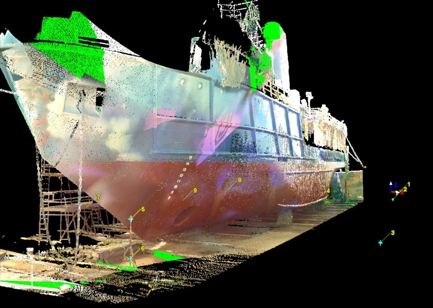
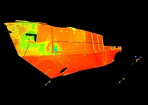
In the above images you can see reference points
on the hull. The points shown are actual balls set on the deck
so that the crew could move to the back of the vessel and scan
from that side. The two scans were merged together and the spotting
points overlaid so that they matched up That data was then taken
by me on a HD drive where I used standard AutoCAD to open it
and segregate sections so that I could trace the lines in AutoCAD
format. |
 |
-
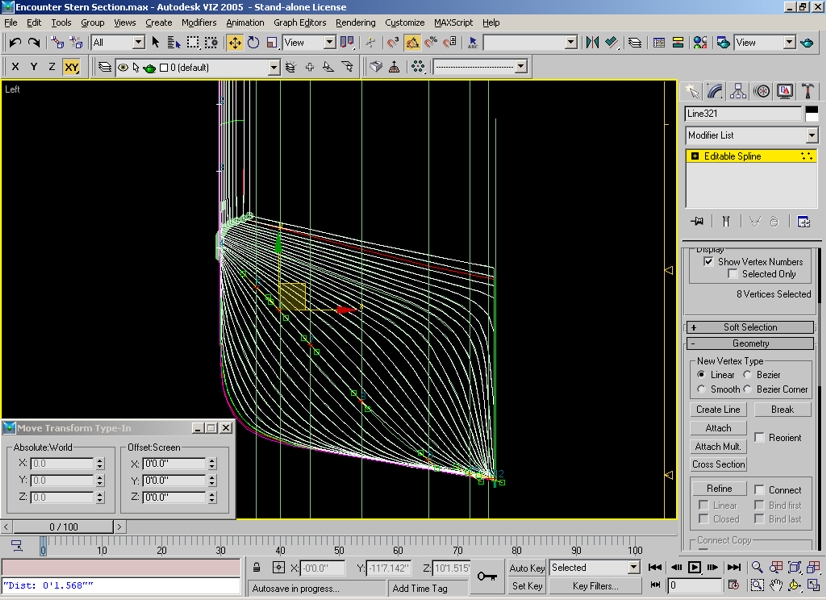
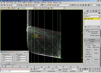 |
Left is a screen capture where the lines were generated
section by section. I will not reveal how I was able to layers
these lines but it was time consuming. Two weeks, 12-16 hours
a day using AutoCAD. I did not have the $14,000.00 for the software
so I had to use what I had. Patience.
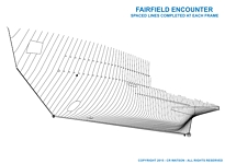
Right is
the line drawing that resulted. While I had included the location
of the pipes using circles, the final decision was to leave the
pipes off and trim those in during installation. |
|
-
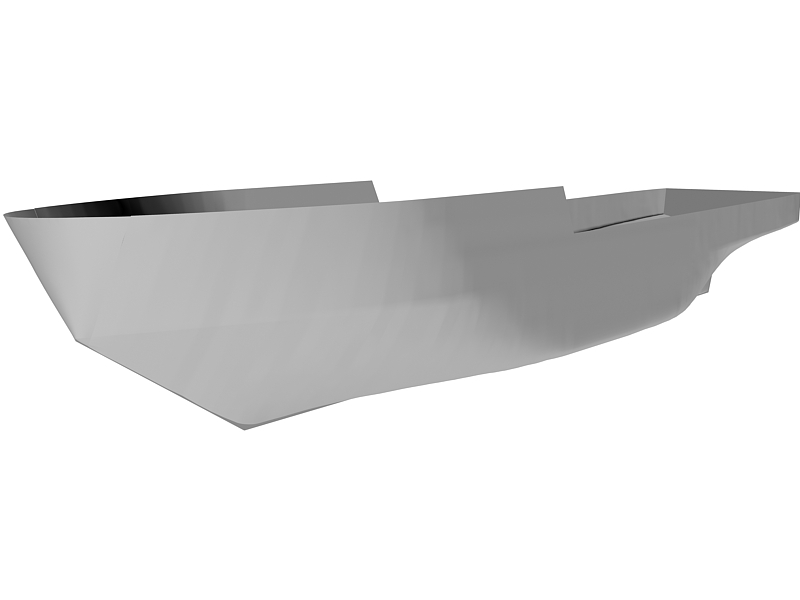
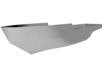 |
Left we have the final assembly generated
from the line drawing in Rhino 3D. The image was done to completion
and the sponsons made and installed. As simple and unimposing
as this image seems, in AutoCAD and Rhino it is to size and detail
sufficient to actually build a matching hull of a sister ship.
Thanks to Roger Fyffe, Naval Architect
who created the final image. Whereas I could generate the line
drawings in 3D my programs would not skin it as he did in Rhino.
|

|
-
- © 1997-2016
c.r. watson - all rights reserved
- The use of any trademarks,
trademarked names, and/or copyrighted information is stated as
a fact of record and is not
- intended to imply
endorsement of any kind. The use of any pictures, writings, or
materials from this site without
- express written consent
of Charles R. Watson dba Watson Enterprises aka MarineImaging.com
is forbidden.
|
|